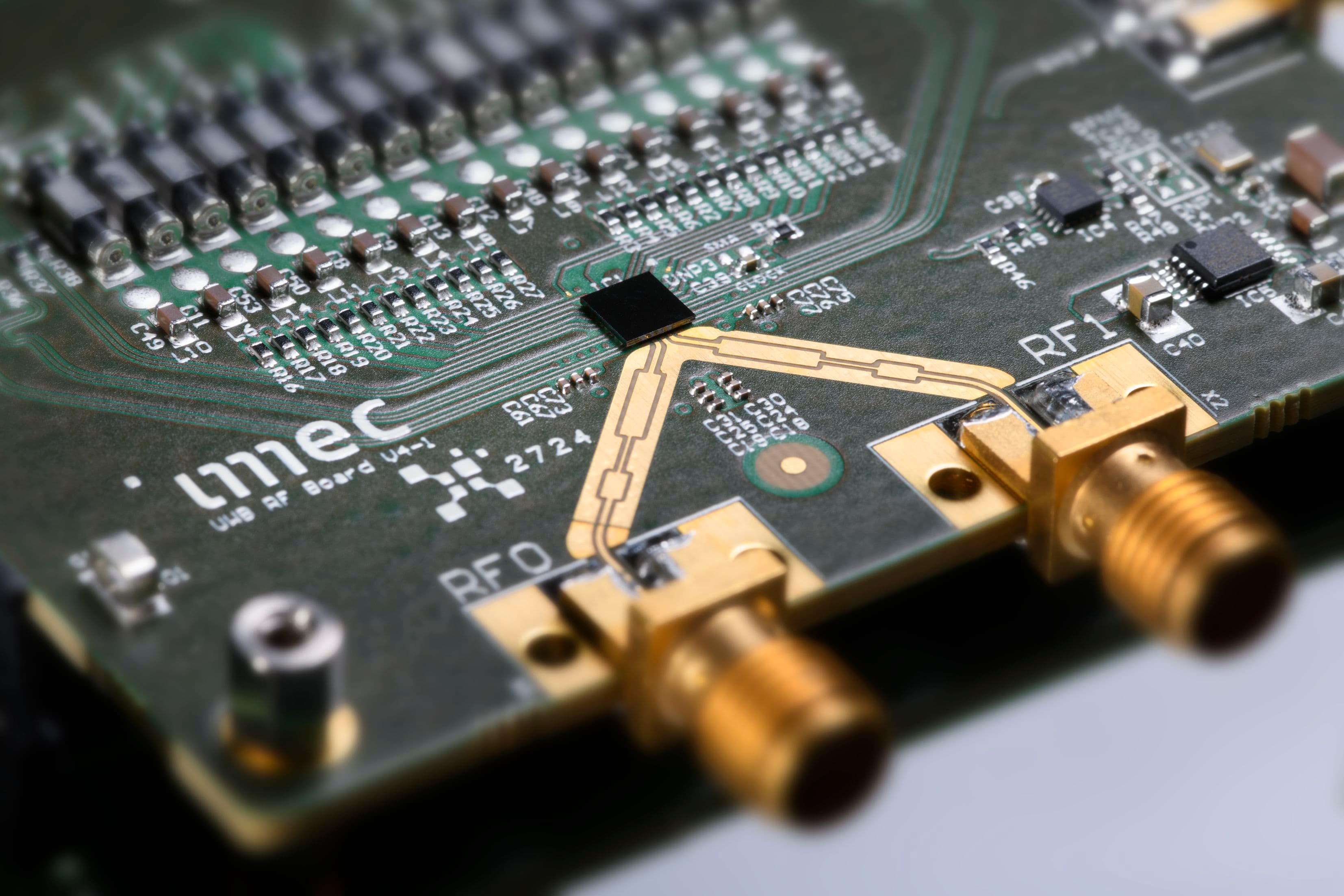
By using 28nm CMOS technology, integrated on-chip antennas and frequency modulation, imec researchers have developed a highly sensitive radar chip that operates on a frequency of 140GHz. The new radar solution is compact, inexpensive, has good depth resolution and angular accuracy. Barend van Liempd, radar program manager, and Kristof Vaesen, senior researcher at imec, tell us about the key components of this new chip and explain what the radar is capable of.
Advances in radar technology make smart applications possible
Since the introduction of the first radar systems in the early 1930s, radar technology has evolved significantly. Across all the years since then, researchers have been able to make radar systems smaller, more power-efficient and cheaper to produce, while at the same time increasing their resolution and enhancing their computing power. These advances, combined with the progress made in chip technology, have led to the first compact, low-power short-range millimeter-wave radars that operate within a frequency range of 30 to 300GHz. These radars are capable of detecting objects over short distances and are being used increasingly to make smart applications possible.
In principle, these radars can be incorporated into just about any object. For example, today you’ll find them embedded in a number of upmarket cars, where they are used to prevent collisions, detect other road-users or as a parking aid. But they can also be used to enhance building security (e.g. for people counting and intruder detection), as well as to monitor the health of car drivers, track the vital signs of patients or detect hand movements, which is a critical part of intuitive human-machine interaction.
To make these and other scenarios possible, more adjustments are currently being made to improve the cost, energy consumption, dimensions and resolution (for example how well they are able to keep two objects apart) of radar systems.
The benefits of high-frequency radar
Although all radar systems operate according to the same basic principle, they are produced in different ‘forms’. For instance, radar systems may differ in the frequency of the carrier wave (e.g. 8GHz, 60GHz, 79GHz and 140GHz), as well as their bandwidth and the type of carrier modulation (frequency or phase-modulation) used. The carrier wave can also be transmitted as a pulse or as a constant signal. Every choice and option has an effect on the cost, dimensions, energy usage and performance of the radar. The application itself defines which type of radar is best used in what situation.
To produce a sensitive, compact radar system capable of detecting very small movements (such as a heartbeat), a high-frequency radar unit is best suited. By using frequencies above 100GHz, the radar can be made broadband – which results in enhanced depth resolution. This depth resolution determines the distance between two objects (in line with the radar) whereby the radar can still perceive the objects as being separate.
With higher frequencies, Doppler shifts – and hence the speed with which the object is moving – can also be measured much more accurately. Doppler shifts are observed as a change in the frequency of the wave reflected by an object that is moving in relation to the radar. For example, for every millimeter of movement, the phase of the received, reflected signal turns the received signal (with a carrier wave frequency of 140GHz) through just under 360 degrees, which means that tiny movements can be measured very accurately.
In addition, the higher the frequency of the carrier wave, the smaller the antennas can be made. For frequencies in excess of 100GHz, the antennas can even be incorporated on to the chip. This makes the radar system ultimately produced more compact and less expensive compared with integrating large antennas off-chip on a PCB. This solution also enables greater bandwidth.
An integrated 140GHz radar chip in 28nm CMOS
Researchers at imec have succeeded in producing an extremely compact radar chip capable of detecting vital signs and small gestures. The radar operates on a frequency of 140GHz and has a range of between 0.15 and 10 meters. It also has a depth resolution better than 15mm and a bandwidth of more than 10GHz.
The carrier wave is transmitted as a frequency-modulated continuous wave (FMCW). The transceiver is made using 28nm CMOS technology, which ensures lower production costs for large volumes.
The key components
The two basic building blocks for the radar are a transceiver with integrated antennas and a phase-locked loop (PLL), which generates the modulated carrier wave.
As the first step in operating the radar, a frequency-modulated continuous wave is transmitted by the PLL – which is also made in 28nm CMOS. This modulates the carrier frequency over a wide bandwidth by way of a linear sawtooth. The speed with which this sawtooth is repeated is known as the ‘chirp’ rate. This chirp rate for the new PLL is particularly high and a bandwidth of 1.5GHz is reached in only 30µs, enabling rapid frequency modulation. The modulated signal, also called the ‘chirp’ signal, is centered around 16GHz.
This central 16GHz chirp signal is sent to the transmitter on the transceiver chip. The signal is then converted to 144GHz, amplified and transmitted via the antenna-on-chip. After being reflected by the object, the signal is picked up by the receiver and multiplied by the original chirp signal. The time it takes for the signal to be received (observed as a frequency offset), provides a measurement for the distance to the object. The analog signal is then converted to a digital signal, from which parameters such as distance and speed can be deduced.
The transceiver performs very well, which is expressed by the exceptionally high EIRP (effective-isotropic-radiated power) of 11dBm for the transmitter and a good noise figure and conversion gain for the receiver (8dB and 84dB respectively). The transceiver chip consumes less than 500mW.
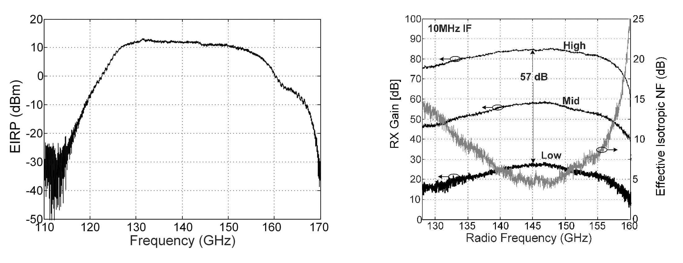
Characteristics of (left) the transmitter and (right) the receiver.
High angular resolution thanks to MIMO
Certain applications, such as gesture recognition, require a minimum angle resolution to be able to capture the gesture in three dimensions. An elegant way of increasing angle resolution is the MIMO radar principle that uses multiple transceiver chips. Based on this principle, the initial chirp signal is sent over a PCB to various transmitters, which then send out (orthogonal) signals simultaneously.
Imec is working on various configurations, including a 2x2 MIMO radar that is just a few square centimeters in size. This radar features 3 transceiver chips in a row and is also called 1x4 virtual MIMO radar. By using the commercial MUSIC algorithm, an angular resolution of 7.5° has been achieved with this MIMO radar.
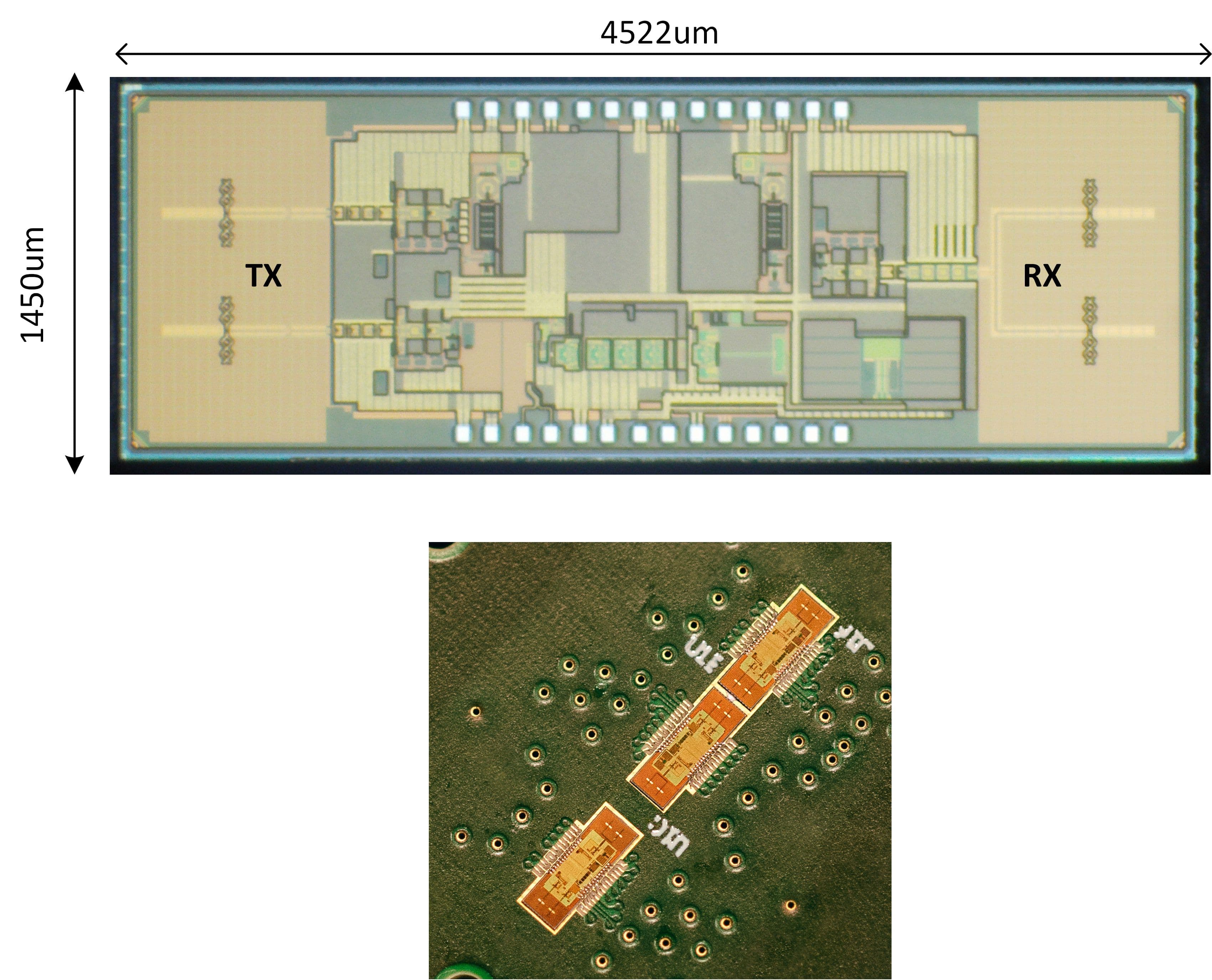
Photo (below) and zoom-in (above) of the MIMO assembly board with the three transceiver chips.
Measuring respiration and heart rate: proof of concept
Experiments have shown that vital signs can also be measured using the radar. This relates in particular to recording respiration and heart rate – for example to monitor the heart rate of patients or to check the heartbeat of a driver while driving.
It has been demonstrated in a series of experiments that the radar is capable of detecting a person’s respiration and heart rates in real-time.
In this instance, the heart rate was measured using micro-skin motions. The imec team is currently working on a wearable demonstrator of its 1x4 MIMO setup.
Readings of a person’s vital signs: (left) respiration and (right) heart rate.
Using the radar for gesture recognition
The team has also investigated to see whether the radar can be used to detect finger and hand gestures to support human-machine interface systems. Whereas a hand gesture typically does not reflect much energy, this very sensitive radar can still detect these movements. This is possibly because the radar’s high range and angular resolution is so sensitive it is able to pick up even small ‘sub’-movements of the finger joints. These result in micro-Doppler signals, which are processed by the radar chip.
Machine-learning techniques were added to this to train the system based on known data. This way, the system is capable of recognizing the Doppler signature of moving objects.
The authors would like to thank Panasonic and Sony for their contribution to this work.
Want to know more?
- Would you like to see the 140GHz radar operating live? Then be sure to visit the imec Future Summits tech exhibition on 14th and 15th May in Antwerp.
- Imec is also developing other radar solutions, such as an 8GHz UWB radar for smart buildings and a 79GHz radar for automotive applications. Contact us via this contact form if you are interested in any of imec’s radar technologies.
- The imec team gave more details about the 140GHz transceiver in an ISSCC paper. If you would like to receive a copy of this paper, you can request one via our contact form.

Kristof Vaesen completed his degree as an industrial engineer in 1996 and in 1998 was awarded an MSc in electrical engineering, both from KU Leuven. In 1998, he began working at imec in the high-density interconnect and systems packaging group, where he worked mainly on the single packaging integration of RF front-ends, focusing on the design of RF building blocks for thin-film RF MCM-D technology. In 2012, he joined imec’s millimeter wave design group. Since then, his research has focused mainly on the design and modeling of millimeter wave passive components and the implementation of CMOS millimeter wave circuit blocks.

Barend van Liempd received his BSc and MSc in electrical engineering from the Technical University Eindhoven, the Netherlands, in 2009 and 2011 respectively. In 2017, he was awarded his doctorate from the Vrije Universiteit Brussel, in conjunction with imec. From 2011 to 2014, he worked as an R&D engineer at imec on multi-standard transceivers. He then became a PhD researcher and later, in 2017, senior researcher. In 2018, he was appointed as program manager radar and he currently leads imec’s radar IC R&D activities. Barend’s interests focus mainly on analog, RF and millimeter wave circuits for wireless applications and sensors. He is the author and co-author of over 30 papers, patents and patent applications. In 2015, he received the NXP Prize at the European Microwave IC (EuMIC) conference.
Published on:
2 May 2019


